
-
-
Acrylic front
-
Wire
-
Distance sensor
-
Screws M3 6mm (Silver) (2x)
-
Sensor holder front (3d Printed)
-
Sensor holder back (3d Printed)
-
-
-
Remove the protective paper from the acrylic.
-
Insert the sensor holder front from the side of the acrylic without the protective paper.
-
Turn the acrylic around and position the sensor holder back aligned with the holes for the screws on the sensor holder front.
-
Position the distance sensor on top of the sensor holder back and align the holes for the screws.
-
Inset and tight the screws.
-
Connect the wire with the red wire starting all the way on the left of the distance sensor.
The sensor holder may be inserted upside down, make sure the 'C' shape sensor holder back fits flush into the front with no gaps otherwise the sensor may be obstructed
Nathan Catlow - Resolved on Release Reply
The center-to-center hole distance is the same on the two 3D printed parts (19.9mm, measured with calipers), but drastically different on the sensor circuit board (21.1mm). There is no way to attach the sensor without modification (DO NOT enlarge the sensor board holes... there are circuit traces very close to the holes).
Guido Kimble - Resolved on Release Reply
-
-
-
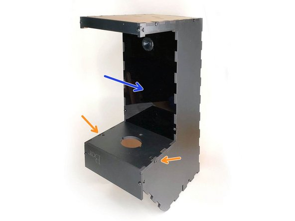
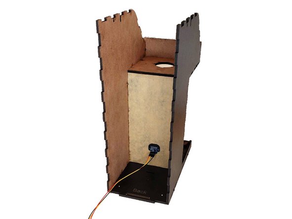
First, position the acrylic front in the case with the sensor facing out.
-
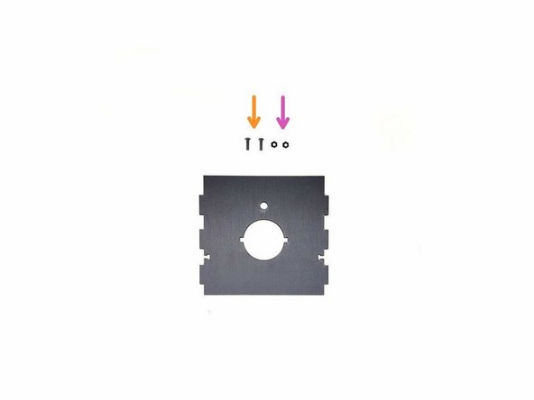
Place the "Top front bottom panel".
-
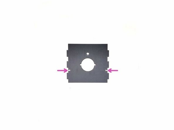
Take the top front bottom panel and insert two M3 nuts.
-
Inset and tight the M3 8mm screws (Black) (2x)
I put this in upside down. My fault, for not noticing the pictures flipped, but these parts could be designed to only be assembled one way (the correct way).
Guido Kimble - Resolved on Release Reply
-
-
-
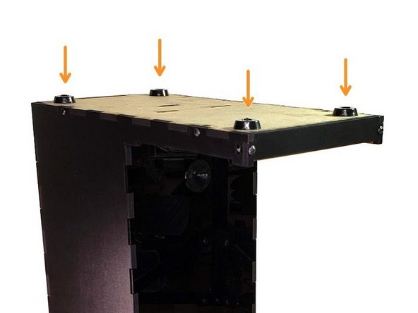
Screws M3 6mm (Silver) (4x)
-
Rubber Pads (4x)
This could have been done earlier, before installing the panel.
Guido Kimble - Resolved on Release Reply
-
-
-
Great job! If you have transparent motors please go to 5a. Pumps column assembly. If your motors are white 5b. Pumps column assembly
-


Cancel: I did not complete this guide.
One other person completed this guide.

One Comment
Some problems on this step. The back panel has evolved to a more elegant design that no longer needs the screws.
Also, the 3D printed sensor holder (the round piece) was too large for the hole and needed sanding. I tried to force it and cracked the acrylic.
Dave@innonavi.com - Resolved on Release Reply
I thinknthe sensor and wire come as one soldered unit now. I don't have any extra, unattached wires.
Guido Kimble - Resolved on Release Reply